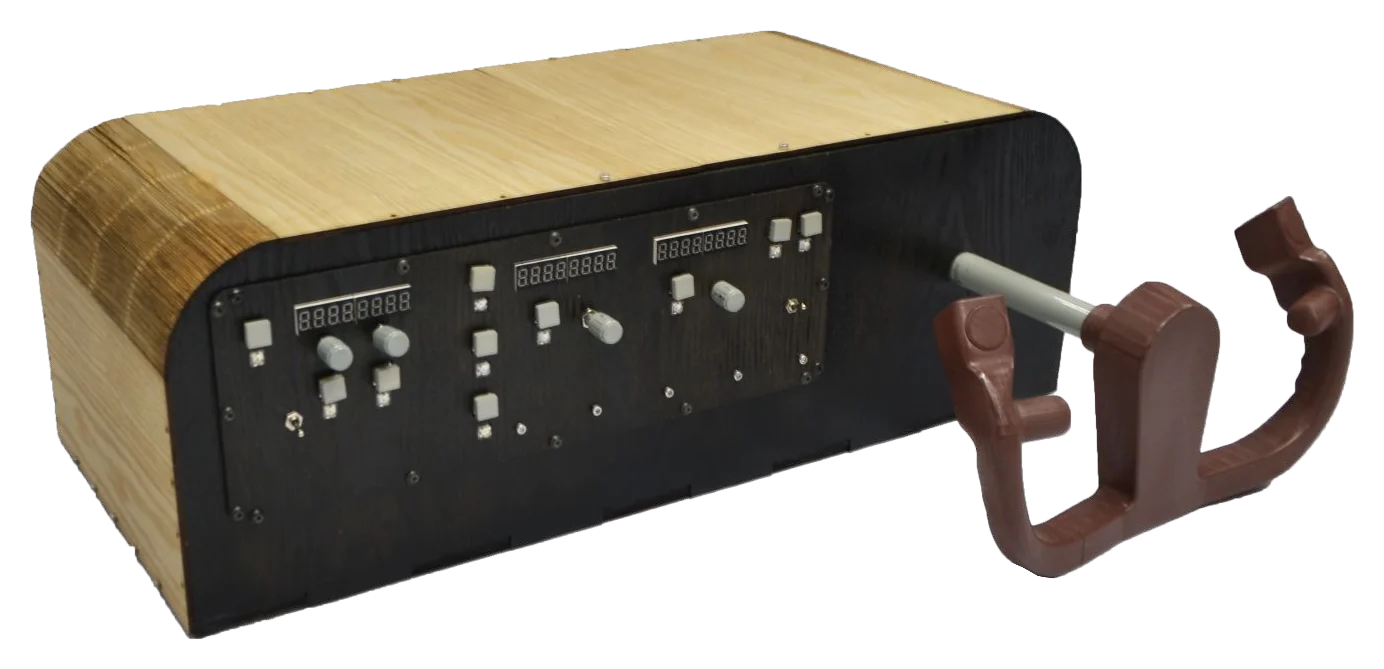
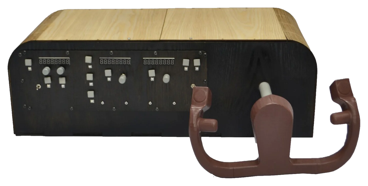
Boeing 737 Yoke and Autopilot Panel
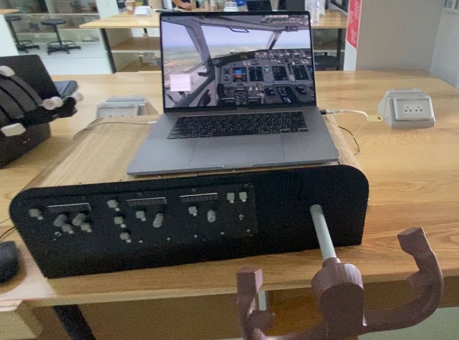
A two-axis flight-sim yoke and an autopilot panel that I designed, built and wired myself. Push and pull for pitch, rotate for roll, each axis sensed through its own mechanism.
What it is
Most people fly a simulator with a keyboard and mouse. I wanted a physical yoke that moves the way the real one does, plus the autopilot panel from the glareshield, so heading, speed, altitude and vertical speed are set by turning real knobs.
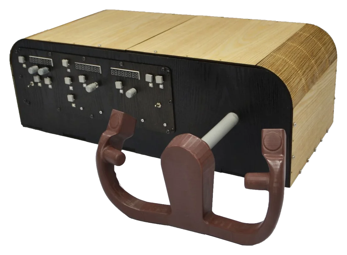
- Yoke. Two degrees of freedom. Push and pull controls pitch, rotation controls roll. Both are calibrated to match the yoke position in the sim.
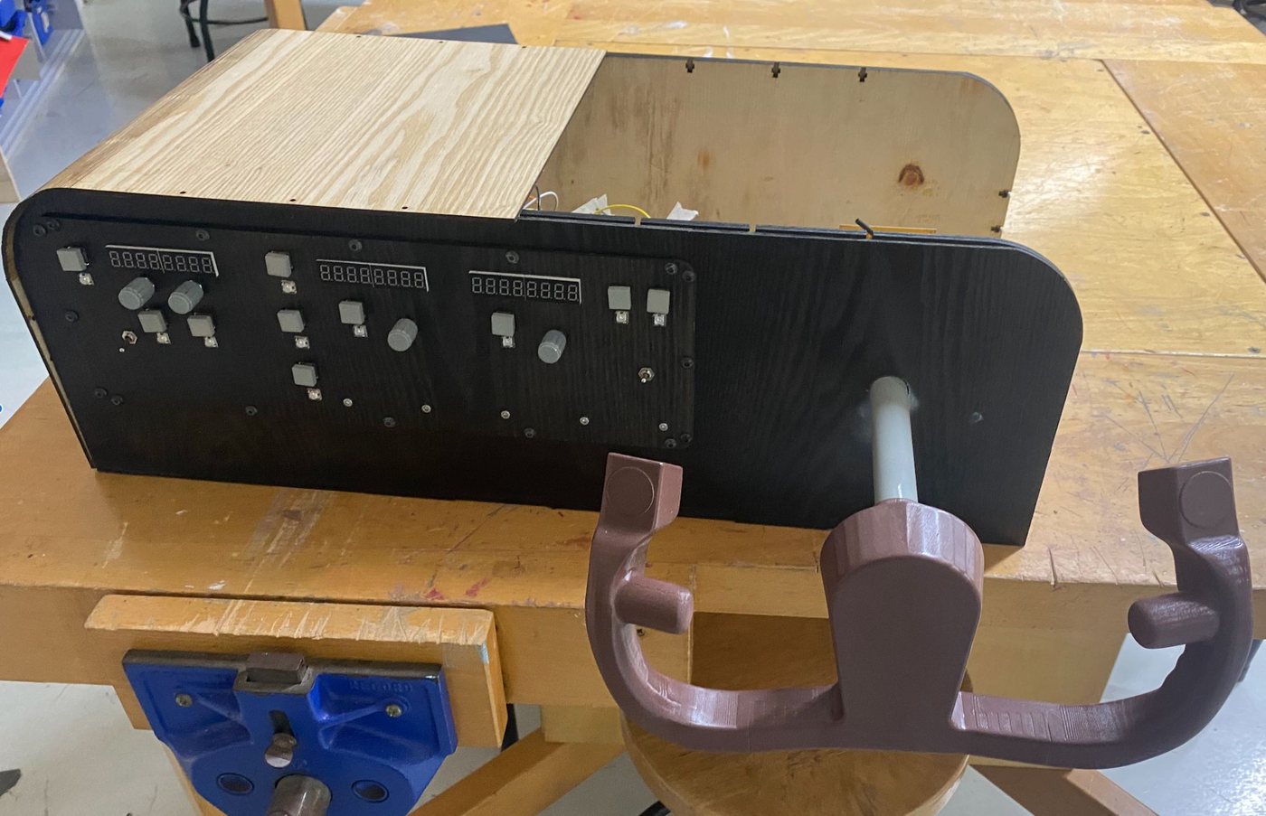
- Autopilot panel. Rotary encoders set heading, airspeed, altitude and vertical speed. Push buttons with LEDs arm each mode. There's also a landing-gear lever.
The mechanism
Pitch: linear motion to rotation
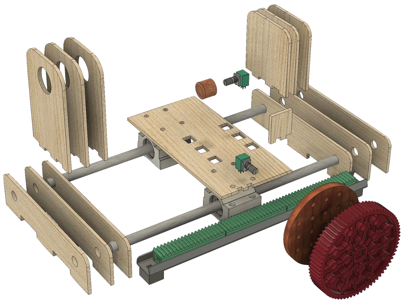
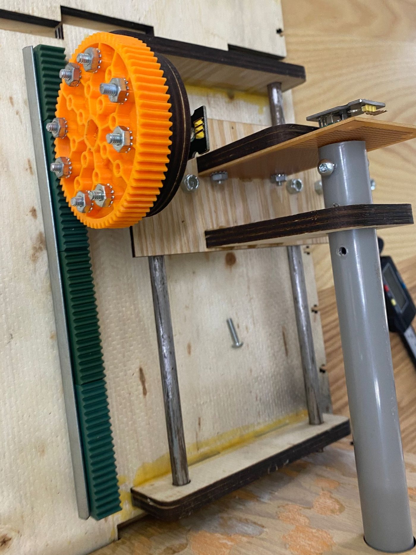
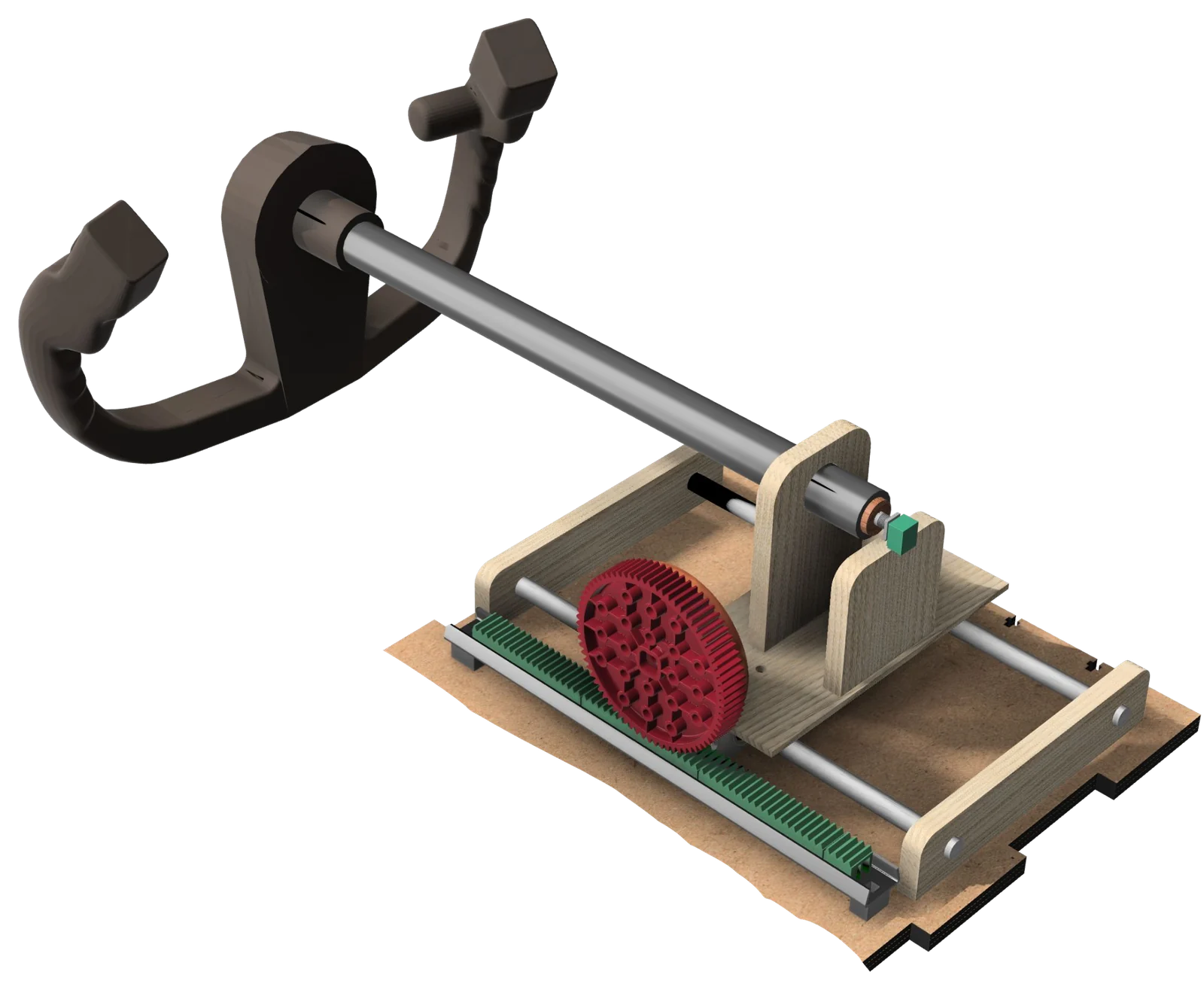
The handle sits on a PVC control rod. The rod is carried by a platform that slides on two steel rods through linear bearings, so push and pull is smooth and doesn't bind. A rack is fixed to the base, and a 72-tooth pinion on the platform rolls along it and turns a potentiometer.
The pinion size was the design decision. A potentiometer only turns through about 300°, so the gear had to be big enough that the yoke's full stroke used most of that range without running past the end stop.
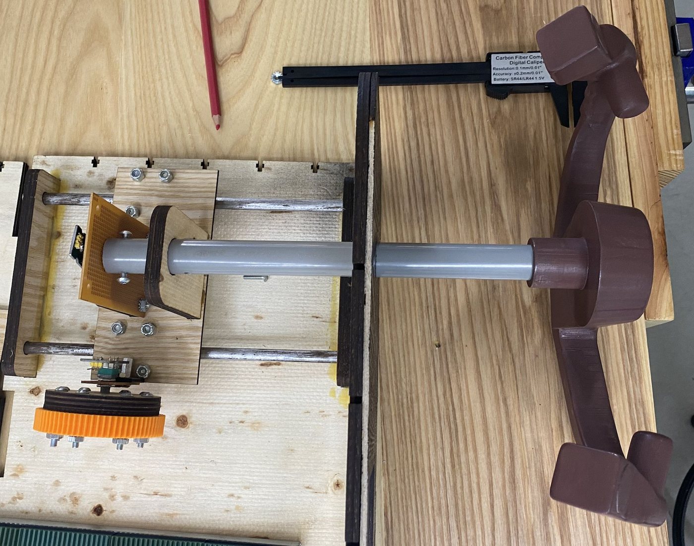
Roll: rotation, sensed directly
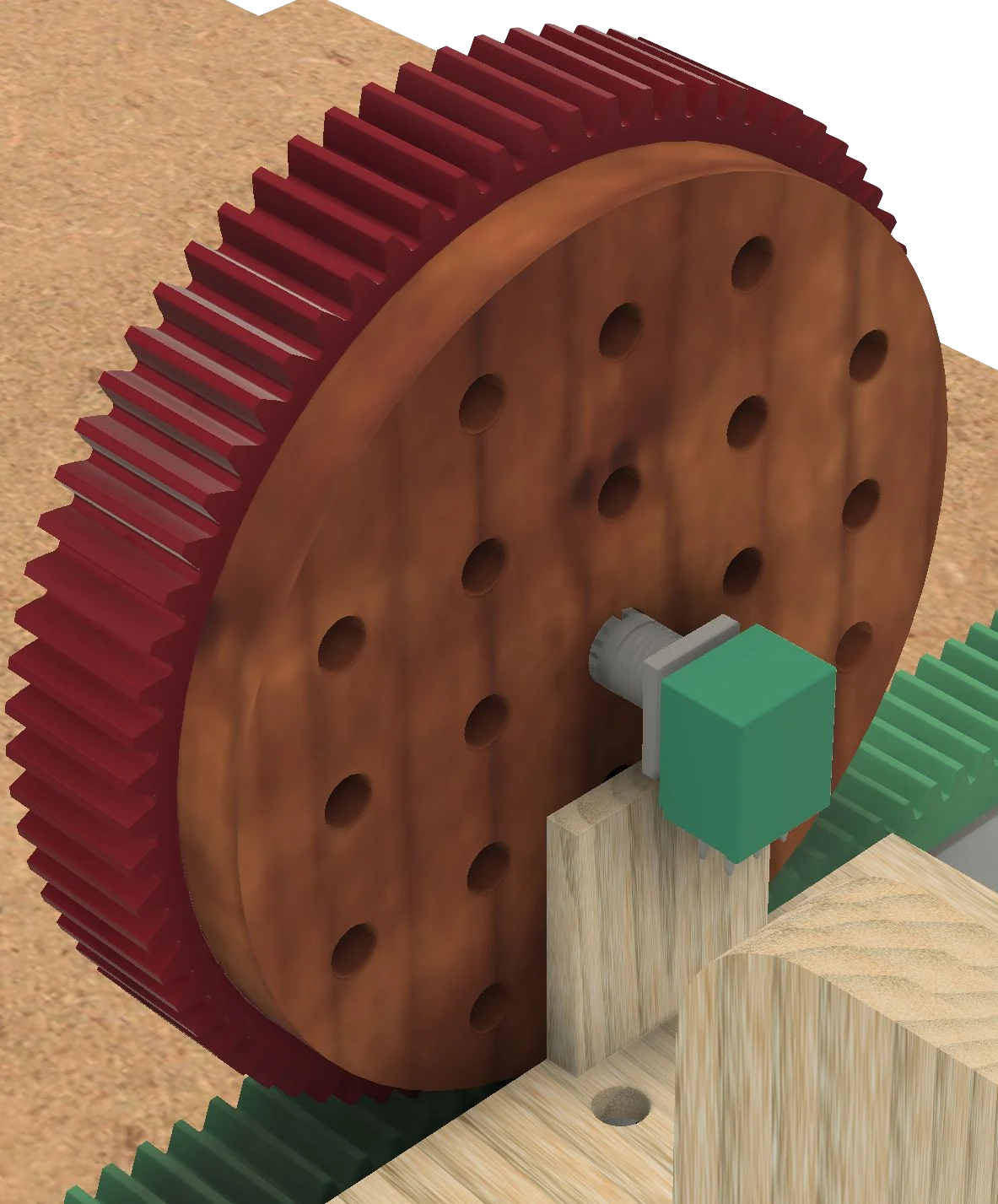
The control rod turns inside its holder. A second potentiometer sits on the end of the rod in a laser-cut mount cut to the shape of the potentiometer shaft, so the shaft is driven by a friction fit and a slot.
Centring and feel
Rubber bands pull the yoke back to centre. The user sets the stiffness by adding or removing bands. It works, but it's the weakest part of the design, and it's the first thing I redesigned (see below).
Electronics
| Part | Qty | Job |
|---|---|---|
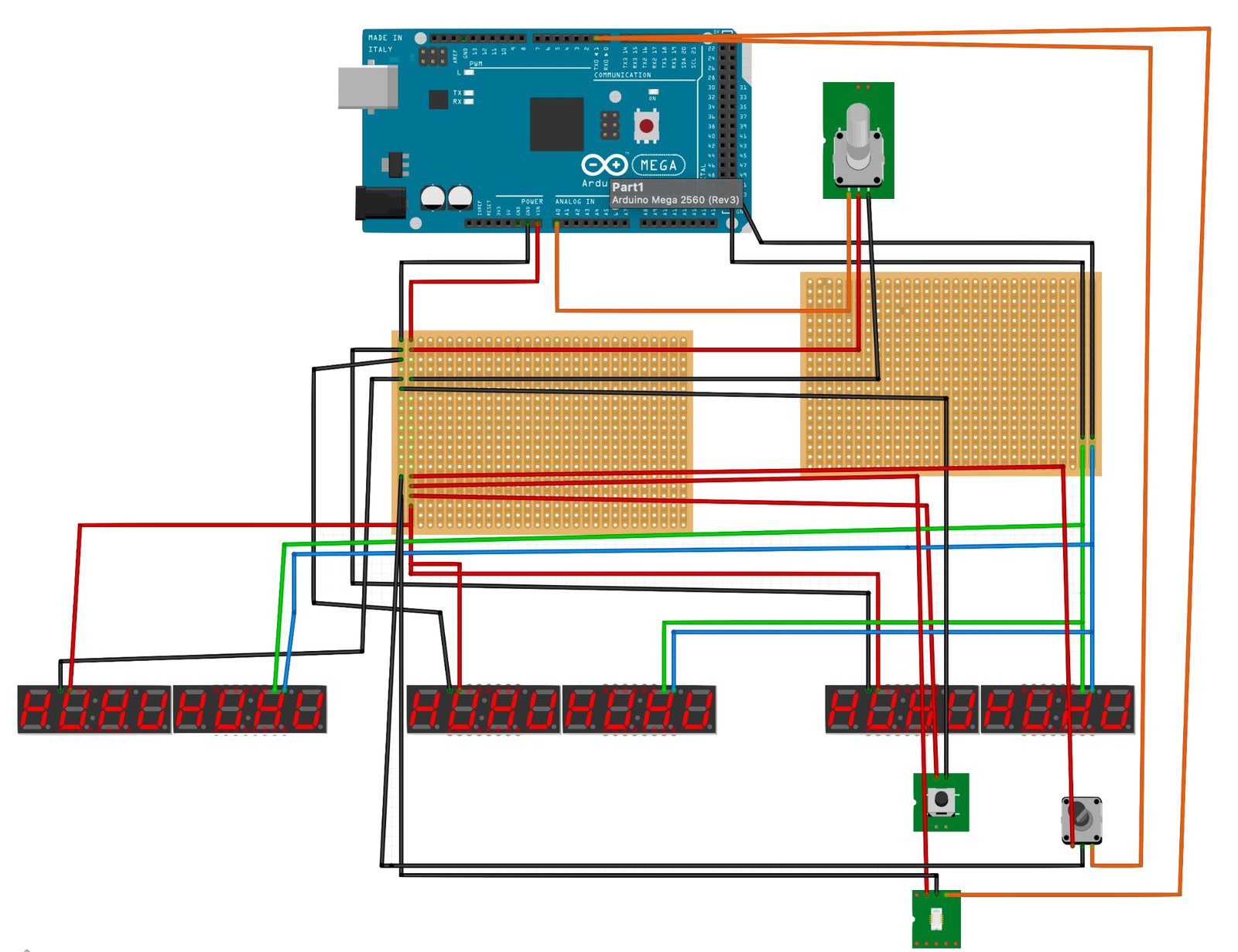
| Arduino Mega | 1 | Reads every input and talks to the flight sim |
| B10k potentiometer | 2 | Pitch and roll position, on analogue inputs |
| Rotary encoder | 4 | Heading, airspeed, altitude, vertical speed |
| Push button + LED | 10 + 10 | Autopilot modes, each with a status light |
| Toggle switch | 2 | Auto-throttle and similar on/off functions |
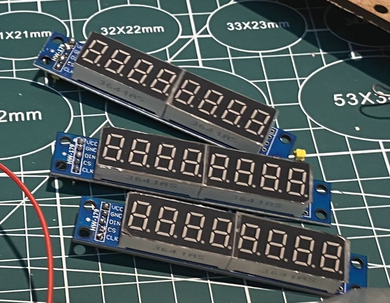
| MAX7219 7-segment display | 3 | Shows the autopilot values |
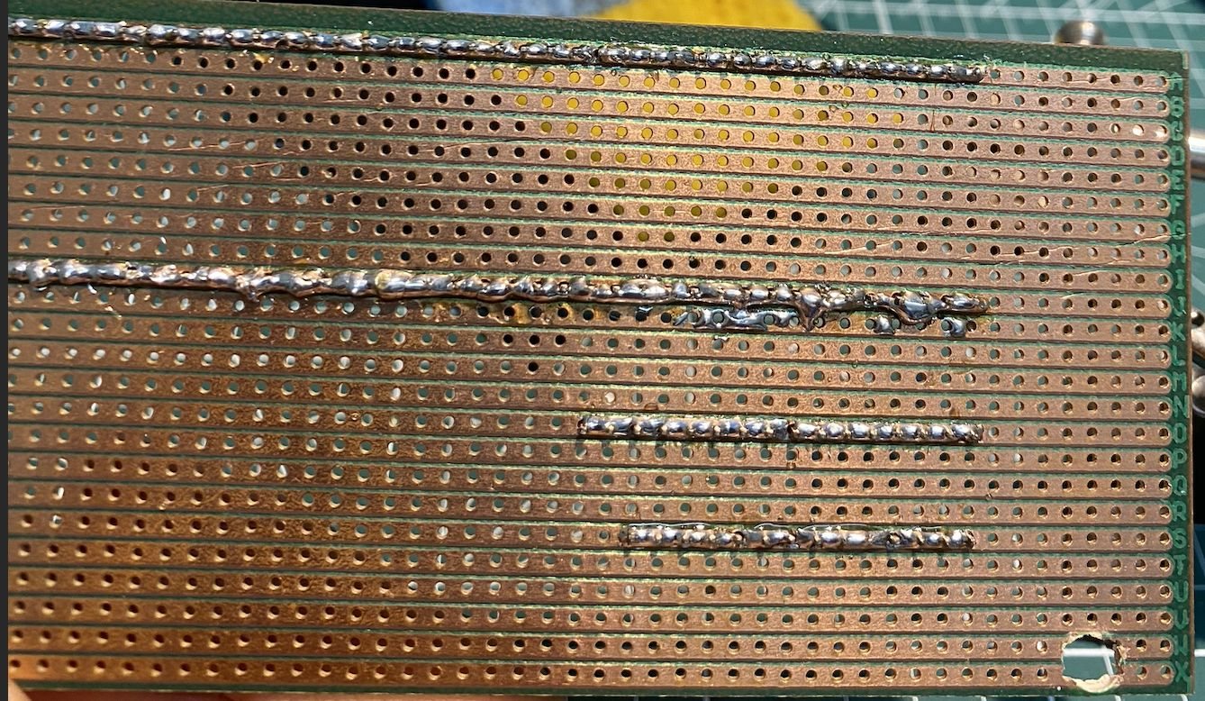
| Stripboard | 1 | 5 V and ground distribution to every component |
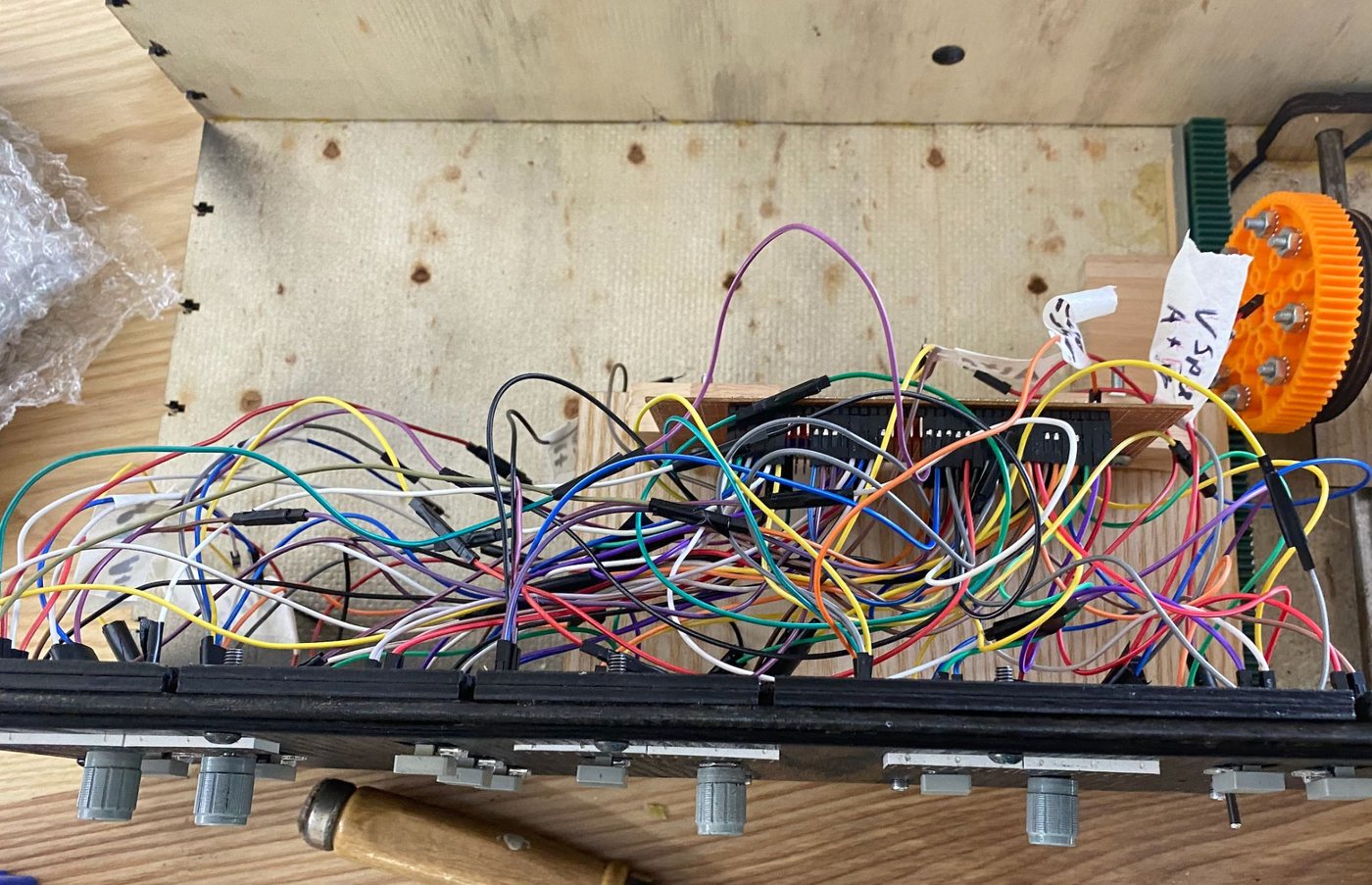
I started on an Arduino Uno and it couldn't hold a stable connection with the sim once the code grew, so I moved to a Mega for the extra memory and pins. Power is distributed on a soldered stripboard, with jumper wires running to the Arduino.
Case and build
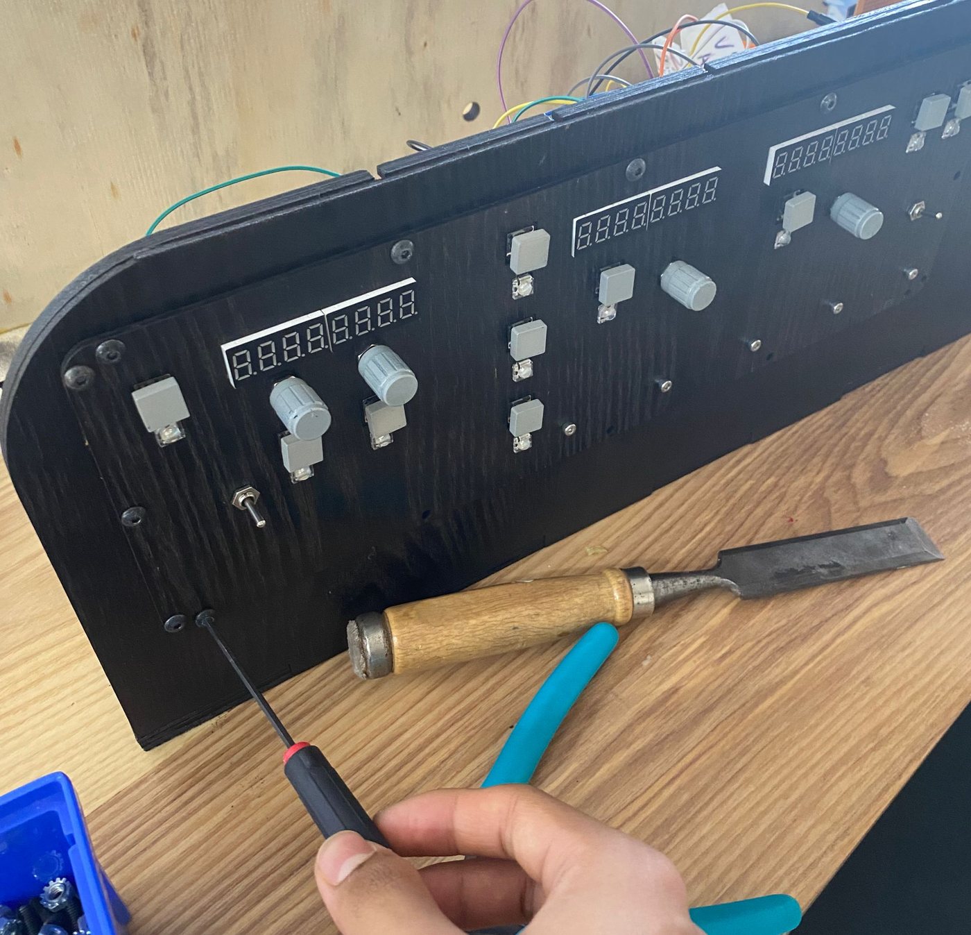
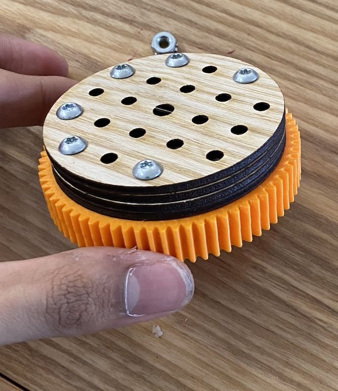
- Plywood case with a laser-cut living hinge that wraps over the top in one piece, finished with beeswax.
- The cover is held by T-nut joints and M3 bolts, so it comes off with an Allen key for repairs and goes back on as many times as you like. Nothing structural is glued shut.
- The case is strong enough to carry the laptop that runs the sim.
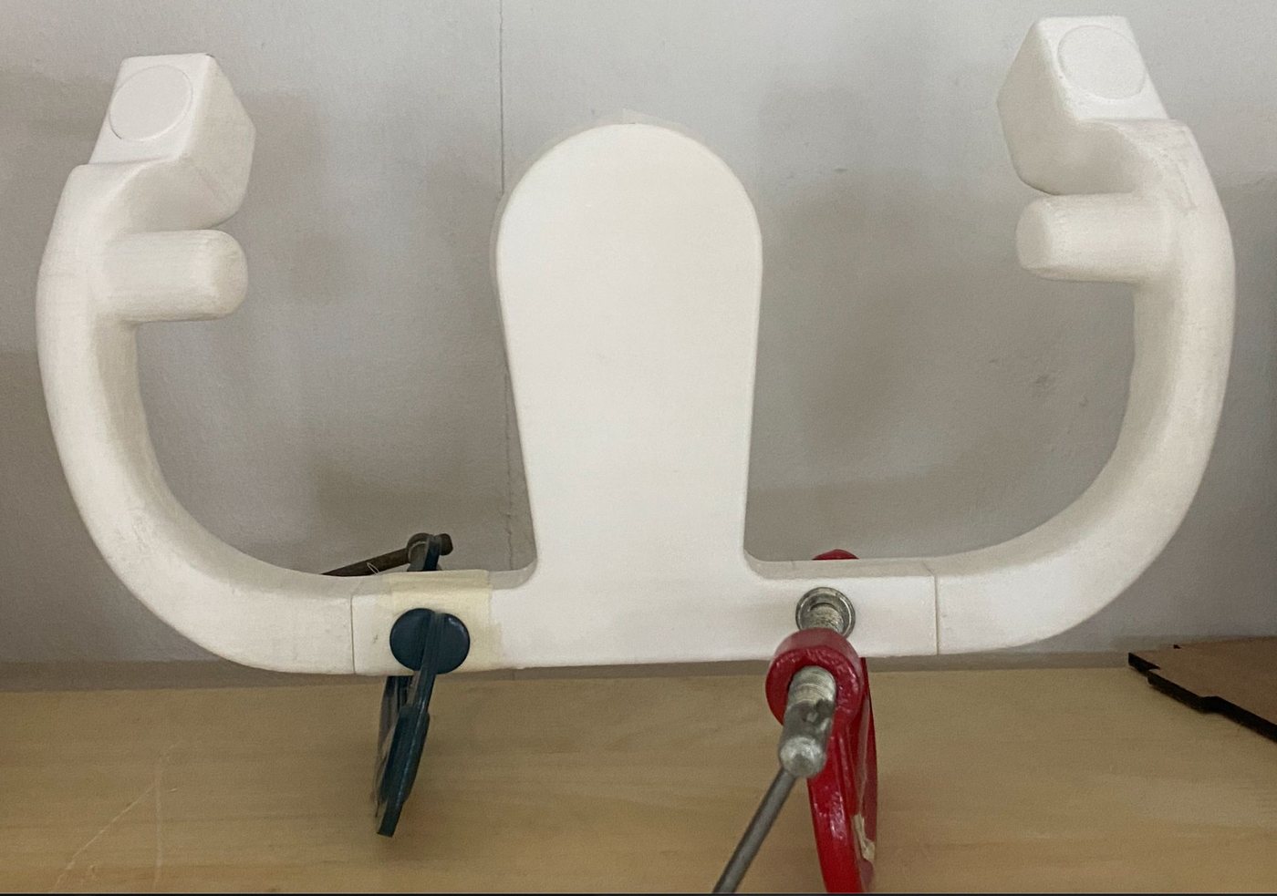
- Handle printed in three parts, sanded, bonded with epoxy and spray painted.
What didn't work, and what I changed
| Problem | Cause | Fix |
|---|---|---|
| The first potentiometer mount caught fire in the laser cutter | Cut lines were too close together | Simpler mount shape with wider spacing |
| Potentiometer wouldn't fix to 3 mm MDF | The threaded section was too short for the nut | Mounted it on 1 mm stripboard |
| Unstable connection to the sim | Not enough memory on the Uno | Moved to an Arduino Mega |
| Displays flicker and lag | Not enough power, and too many displays for the board to drive directly | v2: multiplexer board and a separate supply |
| Yoke feel is static | Rubber bands can't change force with airspeed | v2: stepper-motor force feedback |
Version 2 (designed, not built)
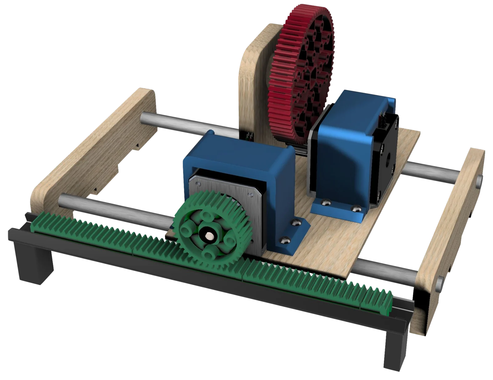
- Two stepper motors, one per axis, in 3D-printed housings on the slider platform. They can be programmed to give different resistance at different times, the way air loads change on a real aircraft.
- A multiplexer board and an external supply for the displays.
- Controls on the handle itself: a hat switch for views, a trigger for radio push-to-talk and an autopilot toggle, so you don't have to let go.
Result
Every function specification was fully met and checked by user testing: two-axis control mapped accurately to the sim, a working autopilot panel with a gear lever, adjustable tension, and a case that opens for repair.