Autonomous VTOL Tailsitter
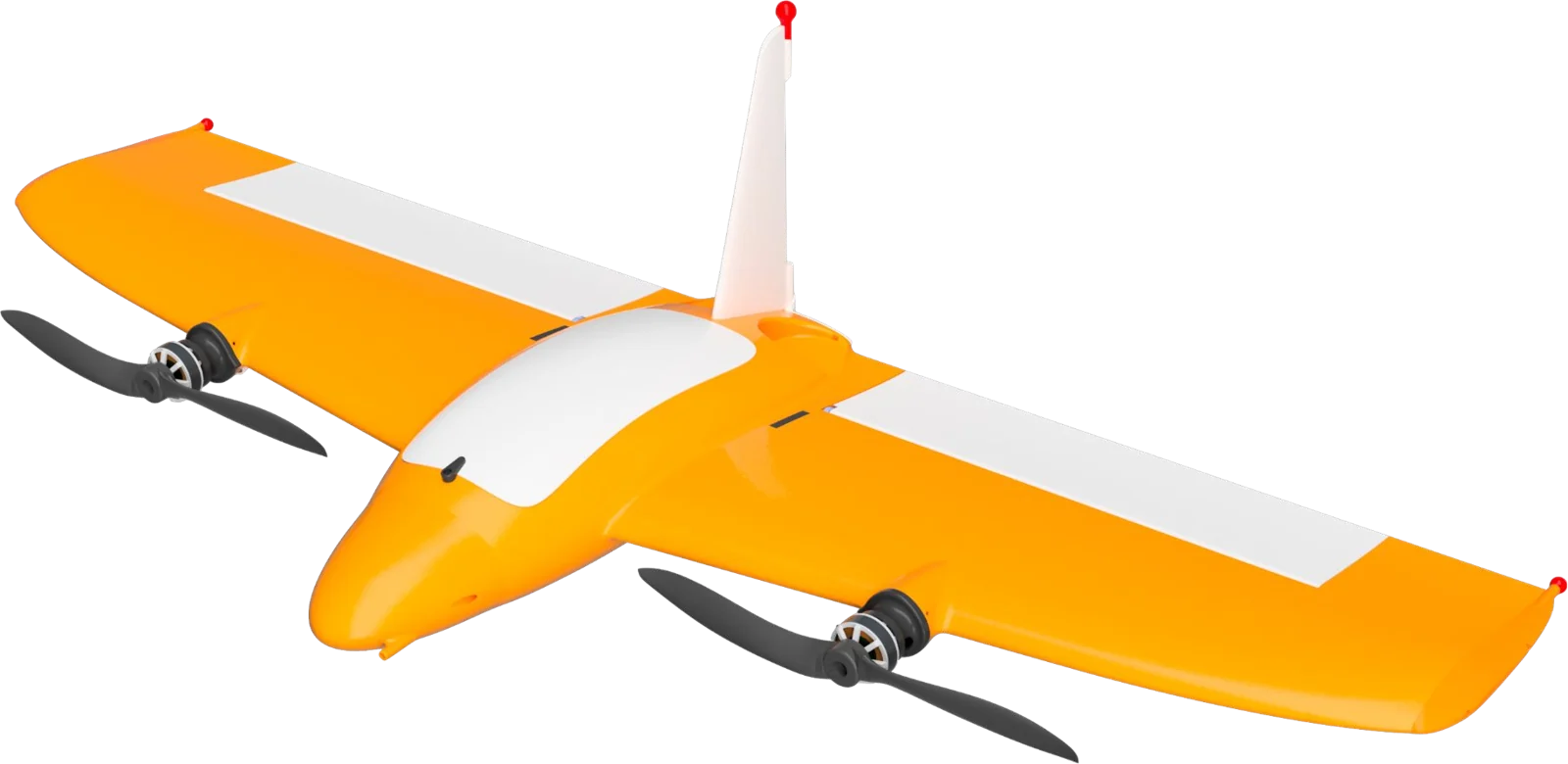
A two-motor flying wing that takes off on its tail, pitches over into wing-borne flight and flies autonomous survey missions. I chose the configuration, then modelled, analysed, printed, wired, tuned and flew it.
The brief
Small Thai rice farms can't see water stress or pests until it shows from the ground, so farmers over-water and over-fertilise to be safe. Three requirements shaped the aircraft.
| Requirement | Why | What it forced |
|---|---|---|
| Map 3 to 5 ha in one flight | That's a typical farm | A wing, for range |
| No runway | Paddy fields don't have one | Vertical take-off and landing |
| No trained pilot | Nobody on the farm flies | Fully autonomous missions |
| Under 3 kg and under 10,000 THB | Weight and cost limits in the brief | Printed airframe, two motors, hobby-grade electronics |
Choosing the configuration
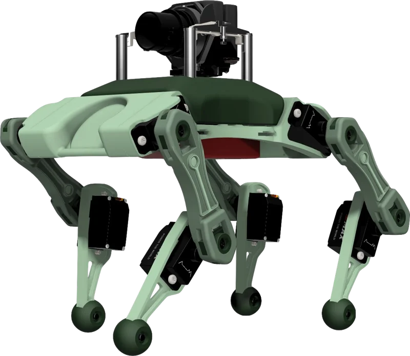
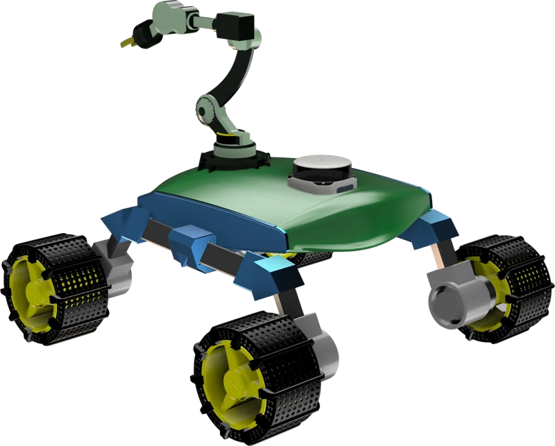
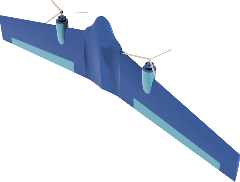
I didn't start with a drone. I sketched ten concepts, from a rover to a floating boat, and scored each against a 23-point specification. The top three got physical prototypes, tested on grass, mud and slopes, checked in FEA and re-scored.
Why a tailsitter
| Configuration | No runway | Cruises on a wing | Motors |
|---|---|---|---|
| Multirotor | Yes | No | 4 |
| Fixed-wing | No | Yes | 1 |
| Quadplane | Yes | Yes | 4 + 1 |
| Tailsitter (mine) | Yes | Yes | 2 |
A quadplane does both jobs but carries four lift motors as dead weight in cruise. A tailsitter uses the same two motors and two elevons for everything. The worked example below is why that matters for range.
L/D ≈ 8 is an assumed value for a small flying wing. That's roughly 8 times less thrust once the wing carries the weight. The catch is that the hard part moves into the transition.
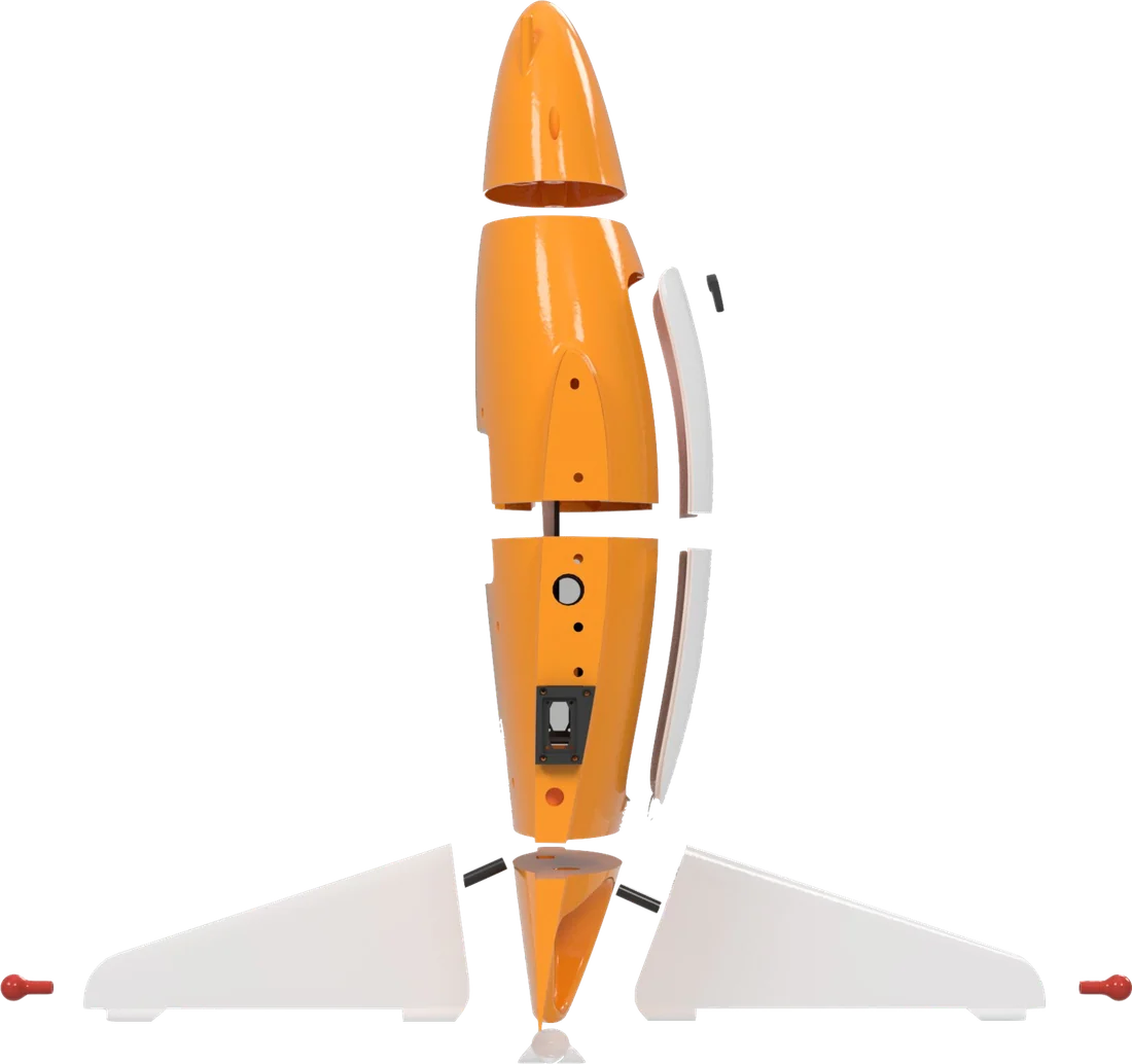
Airframe in Fusion 360
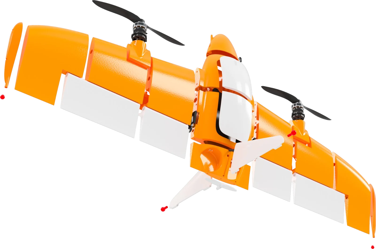
- The fuselage is split into segments on hex bolts, so every part fits a school printer bed and the electronics stay reachable.
- The wings slide onto Ø12 mm carbon spars, so a cracked panel is a swap and not a reprint.
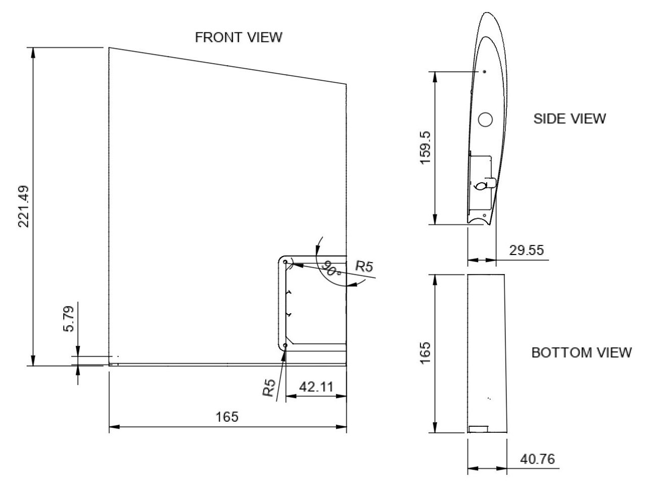
- I drew every part orthographically, 16 unique parts and 25 printed, to check fits before printing.
- Wing root panel: 165 mm chord, R5 fillets around the servo bay. Motor mount: about 77 mm across, and it takes the full thrust load in hover.
Analysis, and what it changed
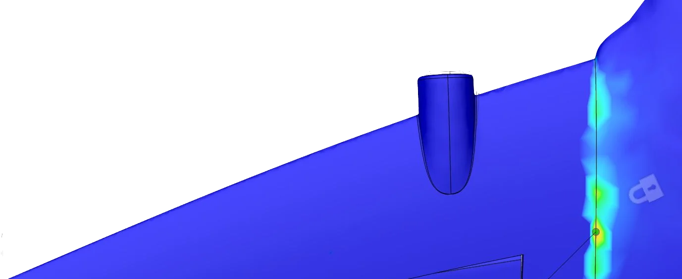
| Test and setup | Finding | Change |
|---|---|---|
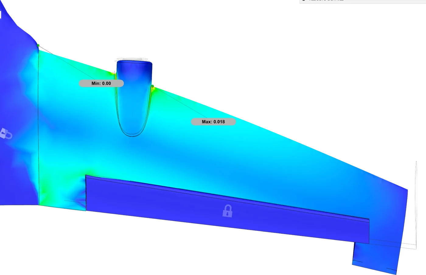
| Wing root FEA: lift and thrust at the tips, motor base fixed | Stress peaks at the root, past what PLA tolerates | Ribs, fillets, root walls 30% thicker |
| Belly FEA: 20 N hard-landing load | Peak at the base plate | TPU feet, dual-wall belly |
| CFD: airflow at 15 m/s cruise | Clean pressure split, tip vortices | Upturned tips, TPU leading edge |
| Bench: 0.5 m drops, 30 elevon hinge cycles | Dents on hard soil; hinge whitening after 25 cycles | Rubber pads, thicker hinge, TPU insert |
Looking back, the FEA peaks sit at the fixed constraints, so they're partly an artefact of how I held the model. A mesh and boundary-condition check is the next step I'd take before trusting those numbers.
Printing and assembly
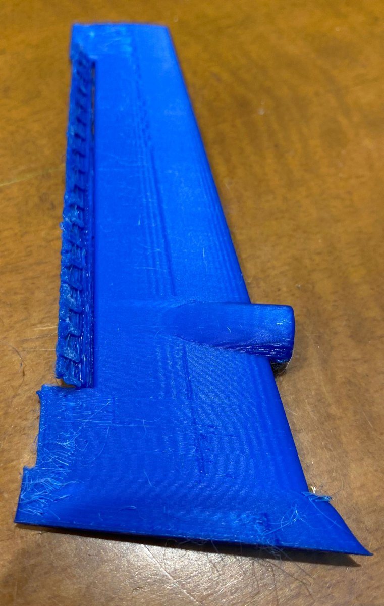
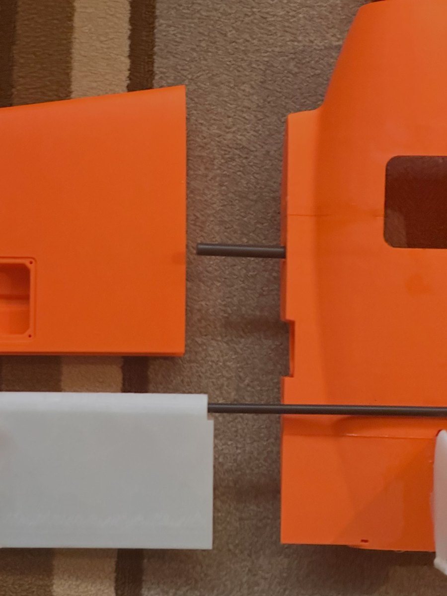
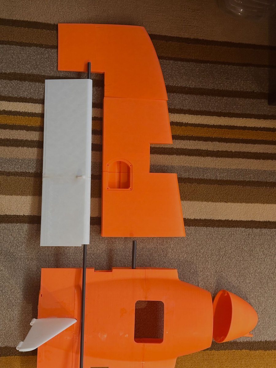
- Sliced in Cura. FDM holds ±0.2 to 0.3 mm, which is enough for the spar sockets and the battery rail.
- About 120 h of printing: 40 h for the fuselage, 60 h for the wings.
- PLA picked by weighted matrix: 20 / 25, against 16 for foam and 15 for carbon nylon, mainly on printability and cost.
- TPU elevons and legs, printed slow and dry, because they need to flex.
- Brass heat-set inserts for M3 threads. Spars epoxied into printed sockets.
- Primed, painted high-visibility orange so you can find it in a green field, then clear-coated. Critical fits checked with calipers.
Electronics and flight stack
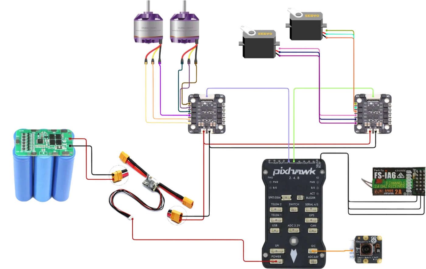
| Layer | What I used |
|---|---|
| Flight controller | Pixhawk running PX4 on NuttX. It has also flown on ArduPilot. |
| Sensing | IMU, barometer, GPS and compass |
| Estimation | EKF2 state estimator |
| Control | Multicopter, fixed-wing and transition controllers |
| Actuation | 2 motors on ESCs, 2 elevon servos |
| Safety | RC override and kill switch |
| Ground station | Mission Planner over MAVLink |
| Power | LiPo through a power module |
Layout and starting parameters referenced the open-source eXplora tailsitter. The airframe is my own design.
Bring-up, in the order I did it
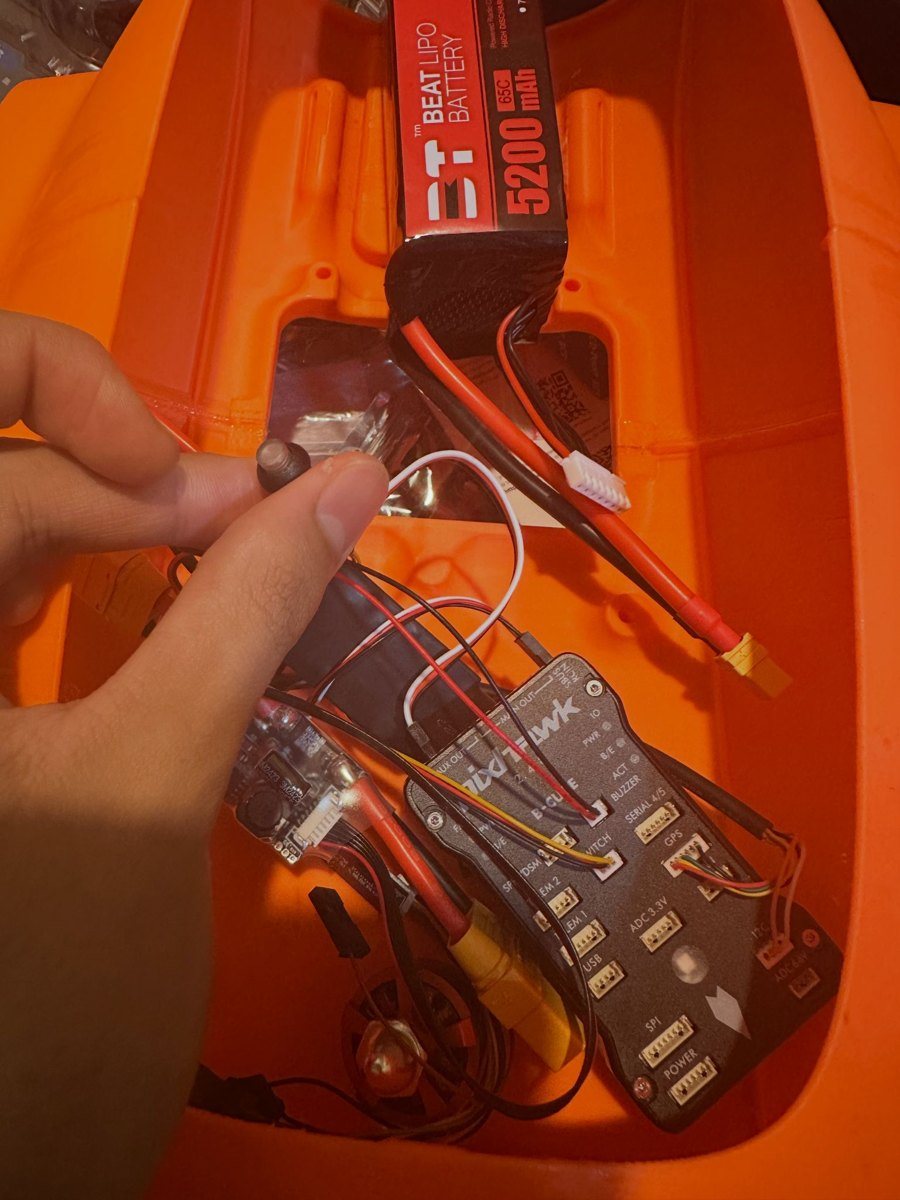
- Mounting. Flight controller on foam pads so motor vibration doesn't corrupt the IMU. GPS on a mast away from the power wires. Camera on silicone dampers.
- Power. Soldered harness, heat-shrink, polarity checked on a multimeter before plugging anything in.
- Firmware. PX4 flashed, tailsitter airframe selected.
- Calibration. Accelerometer, gyro, compass and radio.
- Actuators. Props off: motor order, spin direction, elevon throws. A reversed elevon flips a tailsitter on take-off.
- Safety. Kill switch and failsafes tested at low throttle.
- Hover tuning. Rate PIDs first, then attitude.
- Transition. Transitions at height, then full missions.
Control
Control is a cascade. The mission gives a waypoint, position error becomes a velocity setpoint, velocity becomes an attitude, and attitude becomes body rates. EKF2's estimate feeds back into every loop. I tuned from the inside out: rate loops first, then attitude.
| Loop | Controller | Output |
|---|---|---|
| Mission | Next waypoint | Position setpoint |
| Position | P | Velocity setpoint |
| Velocity | PID | Attitude setpoint |
| Attitude | P | Rate setpoint |
| Body rates | PID | Moments |
| Allocation | Mixer | Motors and elevons |
The actuator mapping is the same in hover and cruise. What changes is how each motion looks from the ground.
| Body axis | Actuator | In hover it looks like | In cruise |
|---|---|---|---|
| Along the fuselage | Elevons opposite | Spinning on the spot | Roll |
| Along the span | Elevons together | Tilting fore and aft | Pitch |
| Out of the top | Differential thrust | Tilting sideways | Yaw |
The elevons only have authority in hover because they sit in the propwash.
Transition as a mode switch
| PX4 parameter | Default | Role |
|---|---|---|
VT_ARSP_BLEND | 8 m/s | Start blending multicopter and fixed-wing control |
VT_ARSP_TRANS | 10 m/s | Switch to fixed-wing |
VT_TRANS_TIMEOUT | 15 s | Abort if the transition is slow |
VT_B_DEC_MSS | 2 m/s² | Back-transition deceleration |
VT_FW_QC_P / _R | off | Quad-chute: drop back to hover if pitch or roll pass a limit |
The back-transition matters most for planning, because the aircraft needs room to slow down.
So the mission has to start the back-transition about 56 m before the pad, on a straight, clear line.
Autonomous survey missions
| Seq | MAVLink command | What it commits to |
|---|---|---|
| 0 | NAV_VTOL_TAKEOFF | Climb, then transition |
| 1 | DO_SET_CAM_TRIGG_DIST | A photo every N metres |
| 2 to 13 | NAV_WAYPOINT | Lawnmower survey lanes |
| 14 | NAV_VTOL_LAND | Back-transition and land |
Sizing the survey grid
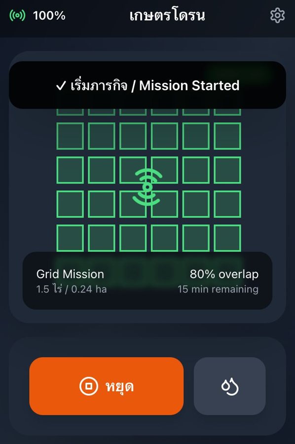
A 150 × 120 m field (about 4.5 acres) is 6 lanes and about 1 km of track, roughly 70 s at 15 m/s. That matches the 4 to 5 acres I covered per flight.
Crop-health sensing
The payload estimates crop health with NDVI. Chlorophyll absorbs red light and healthy leaf structure reflects near-infrared, so a stressed plant reflects less NIR and more red, and its NDVI falls.
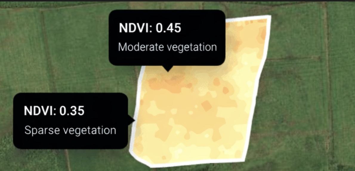
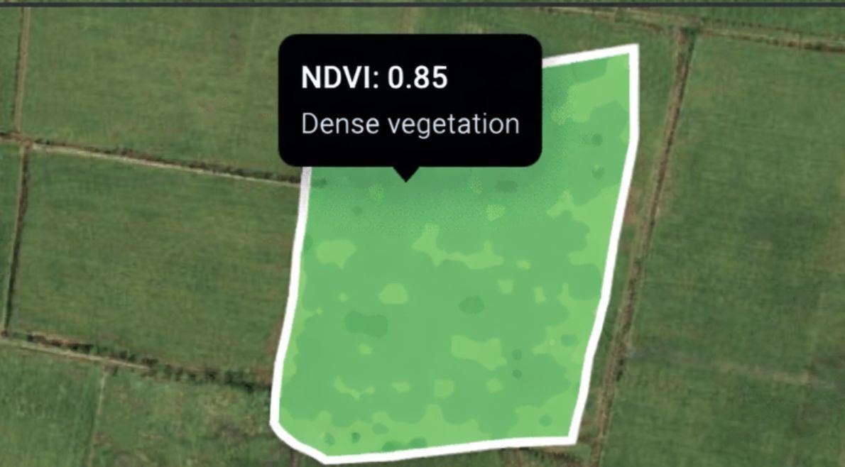
My version used a camera and threshold bands on the microcontroller. The honest limit is that an RGB camera only approximates NDVI. A real measurement needs a near-infrared band.
Test results, and what failed
| Test | Result | What changed |
|---|---|---|
| Crop-stress cards (NDVI) | 4 of 5 right. The miss was at NDVI 0.41, right on my threshold. | Recalibrate thresholds |
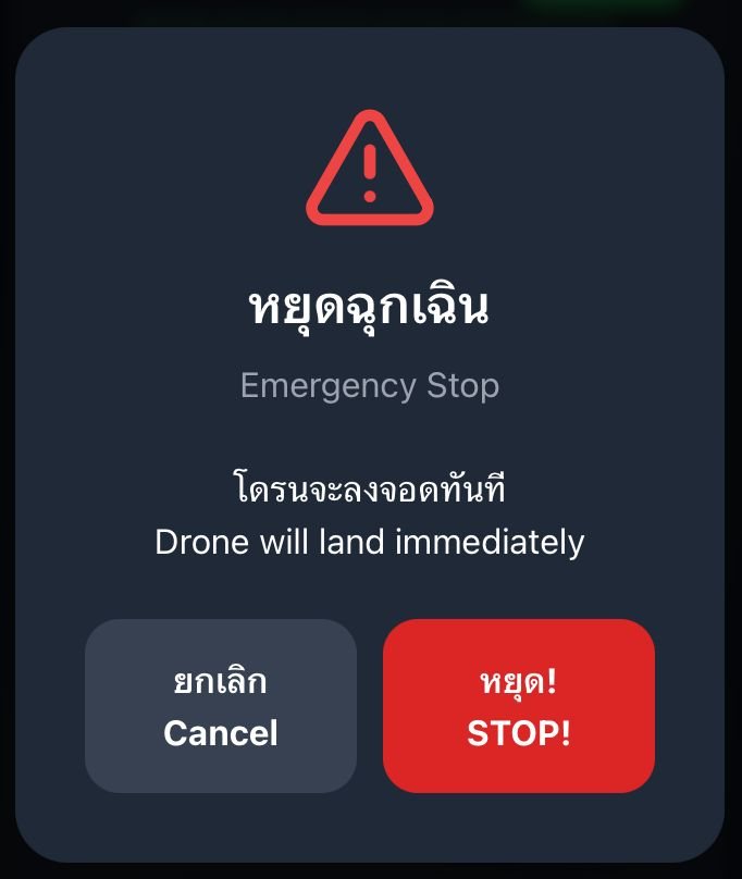
| Kill switch | Motors cut immediately, 3 of 3 trials | Nothing needed |
| Weight | 2.5 kg against a 3 kg limit | Nothing needed |
| Five untrained users | 4 of 5 armed it and set a mode in under 2 min | Clearer start-up cues |
| App icons | 43 of 50 read correctly | Nothing needed |
| Powered VTOL by the school deadline | Not flown in time. I rated it 1 of 5. | Flown since: autonomous survey missions, terrain mapped |