Vibration Belt Tiles
Research in Dr. Bolei Deng's Computational Design and Metamaterial Lab at Georgia Tech. I redesigned the lab's modular vibration tiles so they print cleanly with no supports and press together with no play.
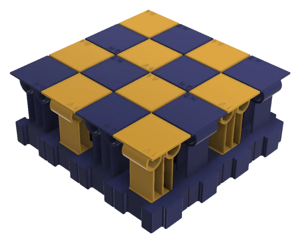
What the tiles are
The belt is a surface made of small tiles. Each tile carries thin printed leaf springs with a mass on top, which act as resonators. The base is vibrated, the resonators respond, and objects on top are moved across the surface. The stiffness comes from the geometry of the leaves, not the material, which is the idea behind mechanical metamaterials.
My job: make them printable
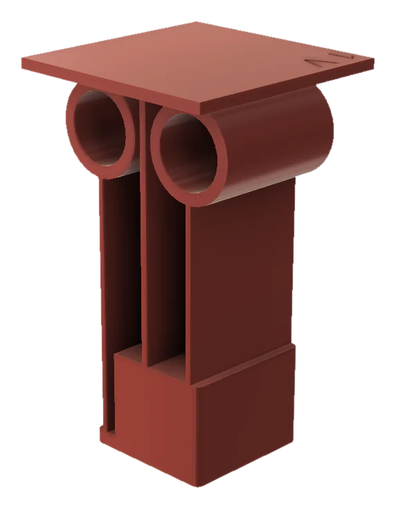
The leaves are 0.8 mm thick. Printed upright they come out weak and stringy, and the tiles need overhangs. The constraint I was given was strict: no supports, and no breakaway or sacrificial structures of any kind. A breakaway frame was tried early on and rejected.
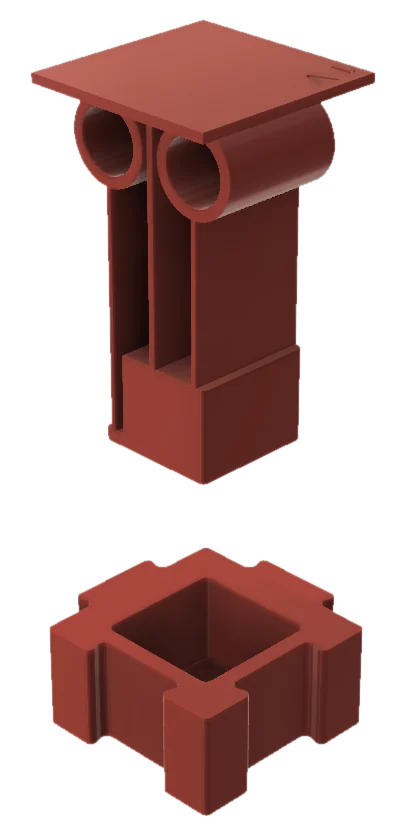
- Split the tile. Each tile is now separate parts printed on their sides, so the layers run along the length of every leaf and nothing overhangs.
- A universal base. Every tile plugs into the same puzzle-piece base: 31.9 mm square on a 32 mm pitch, with a square pocket for the tile's plug.
- Legs start above the pocket. In the first version the leaves began inside the pocket and rubbed on its walls. I moved the root of each leaf above the top of the base and kept the leaf lengths the same, so the dynamics didn't change.
Getting the joints tight
After the first test prints the tiles still had play in the base. I tightened the fit in steps and checked each one on the printer.
| Feature | Before | After |
|---|---|---|
| Socket clearance per side | 0.15 to 0.2 mm | 0.05 mm |
| Press fit | None | Crush bumps, radius 0.3 mm, giving 0.1 mm of interference |
| Lead-in | None | 0.5 mm chamfer so parts start by hand |
| First-layer flare | No allowance | 0.4 mm chamfer to clear the elephant's foot |
I checked in CAD that the only interference between neighbouring parts was the crush bumps, so the press fit is where I designed it to be and nowhere else.
Choosing the joint shape
I compared three joint shapes in 2D plane-stress FEA (PLA, 10 N per joint, 16 mm thick) and kept the mid-side joint.
| Joint | Peak stress, pull | Peak stress, shear |
|---|---|---|
| Corner pinwheel | 6.72 MPa | 5.41 MPa |
| Mid-side (in use) | 1.63 MPa | 3.81 MPa |
| Optimised shape (retired) | 0.57 MPa | 2.70 MPa |
A trade-off I'm still working on
One tile type has a central post that carries a small platform. The first post was a thin upright column that would snap along its layers. I changed it to a flat-printed plate with a crossbar that drops in from the top, which is much stronger. The cost is that the taller post is less stiff, and its sway frequency dropped into the range where the resonators work. If it rings with them, the fix is a shorter column. That's the next test print.
The rest of the lab work
- Designing experiments and testing samples on an Instron to check the lab's simulations.
- Metamaterials with physical intelligence for sensing, an active project in the lab.